

Quite early in the development of Reliq, we had to decide whether it should have a screen at all.
We liked instruments where controls had a fixed place. If you spend enough time with something, eventually you stop reading the labels and your hands start knowing where things are. There is a physical memory to that which we always liked, and because we were still building Reliq primarily for ourselves, we wanted to preserve as much of it as possible.
The problem was the scope we already had in mind. We wanted routing, sequencing, modulation, CV, MIDI and several different ways of looking at the same musical material. We could hide all of this behind colors, LEDs, function buttons and contextual controls, but on the scale we were imagining that would also mean carrying an enormous amount of state in our heads. Every time an encoder changed function or an LED changed meaning, we would have to follow that change mentally as well.
We knew this experience quite well. A blue LED can mean one thing on one page and something completely different somewhere else. A three-letter abbreviation can make perfect sense after reading the manual, only for you to stare at it six months later wondering what it meant again. None of this is necessarily bad design, especially on smaller instruments, but with the scope we had for Reliq it felt like it could very quickly become another large layer to memorize on top of the music itself.
We were also quite conscious of the limitations computers had for us as musical instruments.
A mouse and keyboard were not how we wanted to perform, and the general-purpose nature of a computer came with plenty of distractions and compromises of its own. But there was one thing computers were exceptionally good at: overview.
You could look at a large timeline and immediately know where you were. You could see several tracks at once, read full names, keep larger structures visible while changing something very specific, and move around without memorizing a long sequence of button presses.
That bird's-eye view was something we really wanted.
Around the same time, we were experimenting with what eventually became Reliq's 16 × 16 pad grid.
We liked the logic of old matrix systems, where rows and columns create clear spatial relationships, and we thought that principle could be pushed much further. A large mixer can look complicated when you first sit in front of it, but once you understand one channel strip, the rest becomes much easier because the same relationship repeats physically.
We really liked that idea for Reliq. The pad grid could remain a fixed landscape under our hands, while a display could explain what that landscape represented at any given moment and still show enough of the instrument around it to keep our bearings. If the information for an input appeared directly above the corresponding physical column, for example, we would not have to read "Input 2" somewhere and then search around for Input 2. Our eyes could simply follow the same line down.
None of this was fixed yet. We were experimenting and moving things around constantly, but the combination seemed powerful enough that we wanted to have a proper go at it. It also suggested something quite practical: if the screen was going to participate in the same physical layout as the grid, it probably had to be roughly the same width.
We thought this part would be easy.
By 2020, screens were everywhere. Phones and laptops had beautiful high-resolution panels, cars were filling their dashboards with them, and displays existed in almost every shape and size you could imagine. We did not see many of them on electronic music instruments, but we assumed there were fairly sensible reasons for that. Smaller products cost less, occupy less desk space, are easier to transport and generally make much more commercial sense.
There was also a technical explanation that we were starting to understand. Musical instruments often rely on smaller real-time processors because they are predictable and excellent at timing, while rich graphical interfaces are much more natural on application-class processors. Choosing one often made the other side harder. By then, we were already sketching an architecture for Reliq where those jobs would not necessarily have to live in the same place, so we thought we might have an opportunity to approach the display differently.
In our infinite wisdom, one of the first ideas was simply: why don't we have a panel made in exactly the dimensions we want?
That thought survived approximately until we learned how LCD panels are actually manufactured.
There are only a small number of companies in the world producing panels at that level, and their customers are enormous technology companies ordering at an equally enormous scale. We wanted a few prototypes. We were not a tech conglomerate planning to manufacture half a million identical displays over the next several years.
A custom panel was completely out of the question.
The only realistic way forward was to find a panel that worked for our needs and then build the rest ourselves.
That was when we started learning how different a bare display panel is from a finished monitor.
A modern embedded panel normally receives a continuous stream of pixel data over high-speed electrical links. Protocol families such as MIPI DSI or embedded DisplayPort are examples of this kind of transport, although the exact implementation varies enormously from panel to panel.
At those speeds, electrical noise becomes a serious concern. Signals can change billions of times per second, and even very small disturbances in the board, connector or surrounding circuitry can start affecting their integrity.
This is why these links commonly use differential pairs: two conductors carry opposite versions of the same signal, allowing noise picked up by both to be largely cancelled at the receiving end.
But the electrical lanes are only one layer. Somewhere in memory there first needs to be an image, usually stored in a framebuffer, which is basically "a portion of RAM containing a bitmap that drives a video display" [source: Lenovo]. Hardware then has to read that framebuffer continuously, serialize the pixel data, send it at exactly the rate the panel expects and keep the whole thing synchronized line by line and frame by frame. The panel also needs the correct power rails, initialization sequence, backlight circuitry and timing parameters before it will show anything useful.
We knew almost none of this when we started looking.
After a long search, we eventually found a panel that was close enough to the first dimensions we were experimenting with.
It was not the display Reliq has today and its resolution was considerably lower, around the 720-class we were looking at then, but it was something we could start working with.
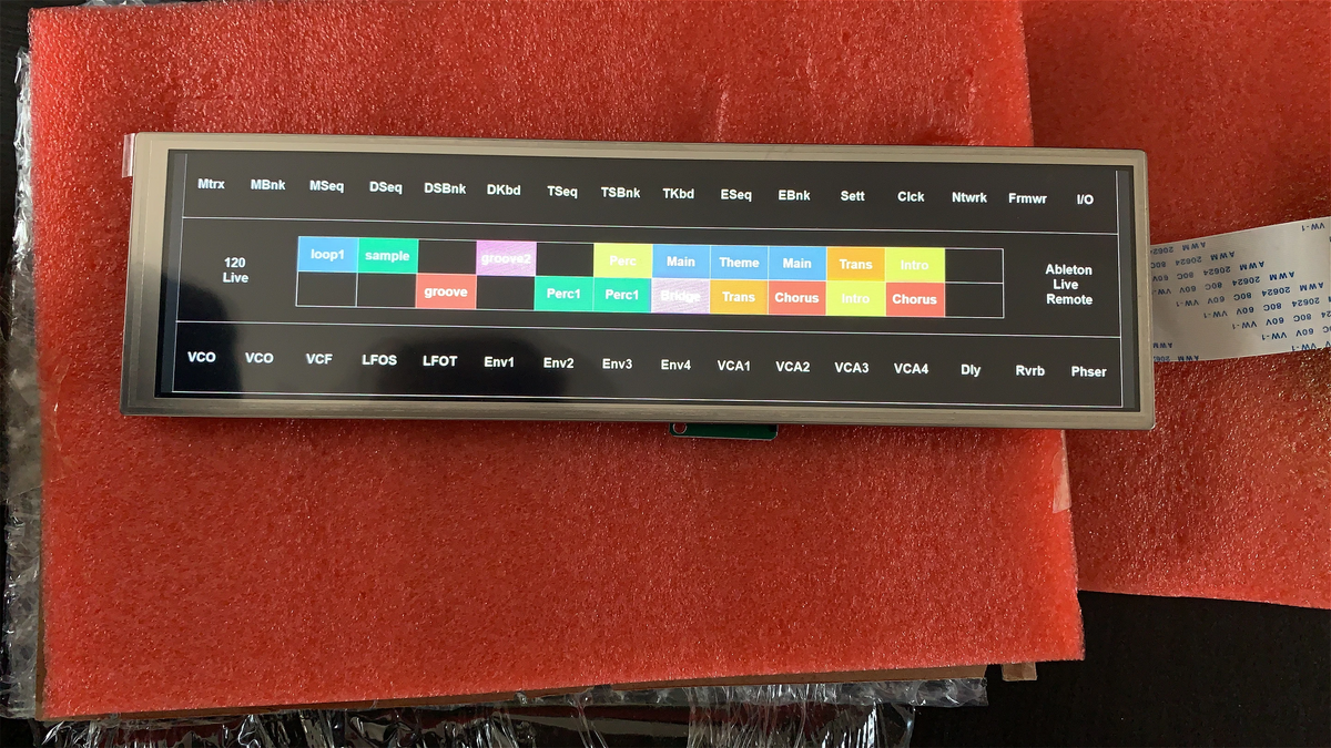
We tried it with different hardware and processors and repeatedly got nowhere. No image, no useful output, just a panel sitting on the desk looking exactly as it had before we connected anything to it.
Getting enough documentation to understand why became another long journey. The display industry is surprisingly secretive, with technical information often sitting behind several layers of NDA agreements, supplier relationships and manufacturer approvals.
Even after signing the necessary paperwork, access does not always happen at once. Suppliers need to understand who you are, what you are actually building and why you need a particular piece of information before more detailed documentation starts becoming available.
I remember one Saturday night particularly well. The panel was on my desk and I was going through yet another combination of hardware and software, trying once again to get the first image onto it. The supplier had sent us an initialization example, so I started checking it carefully, line by line.
The first line said:
force_trubo
It was supposed to say:
force_turbo
The R and U were simply the wrong way around.
That line became a small piece of Reliq folklore afterwards. As I continued through the example, there were more basic problems, and eventually it became clear that this particular script had never actually been compiled in the configuration we had received it for.
To be fair, this sort of thing is not especially exotic in embedded development. Reference code is often written around one particular evaluation board, processor revision or internal test setup, and adapting it is part of the job.
What mattered to us was the realization that there was no complete implementation waiting somewhere for us to discover.
We could use existing work as a starting point, but our dimensions, architecture and requirements were different enough that sooner or later we would have to take ownership of the whole path ourselves.
I sent Michele a very long and fairly frustrated message that night.
There is quite a lot involved in convincing a bare display panel to show even the simplest image. We had to understand its timing, initialize it correctly, provide the right power, control the backlight and make sure the pixel stream arriving at the panel actually matched what it expected. So we started working through those pieces ourselves and slowly replacing assumptions with things we could test.
After weeks of trial and error, we finally got something.
The first image was a basic color test. That very quickly became one of those little rotating 3D GLSL (OpenGL Shading Language) cubes you see in graphics demos.
It was absolutely glorious.
After all those months, seeing that little cube move felt like a ridiculous achievement. I called my partner and some friends from the next room to come over and look at it, completely convinced that everybody was about to appreciate this technological miracle as much as I did.
They looked at it.
"Oh. Nice screen."
Fair enough.
From their side, it was a screen displaying a cube. There was no reason to see the months of documentation, timings, hardware and debugging underneath it.
Technology has this funny quality where something can be incredibly difficult right up until the moment it works, and then it suddenly looks completely obvious.
Still, I have to admit that I would have been slightly happier if the cube had received a tiny bit more respect.
In any case, I immediately went upstairs to Zois (Reliq's UX/UI wizard). We happened to be neighbours back then, which meant that quite a lot of Reliq development involved somebody knocking on somebody else's door at strange hours with a PCB or a piece of code that had finally done something interesting.
I told him the screen was working. He came downstairs, saw the cube and got as excited as I was.
We had a few drinks and celebrated that night.
There were quite a few moments like this in those years.
Something would finally work after weeks or months of frustration, and for a few hours it felt like the greatest achievement in the world. Then the next morning, we would discover the next impossible problem.
That rhythm of getting stuck, figuring something out and celebrating even the smallest victories is still one of the things that keeps us excited about Reliq to this day.
By then we also had prototypes of the pad grid and some of the matrix hardware, which meant we could finally start putting these separate ideas together into something resembling an instrument.
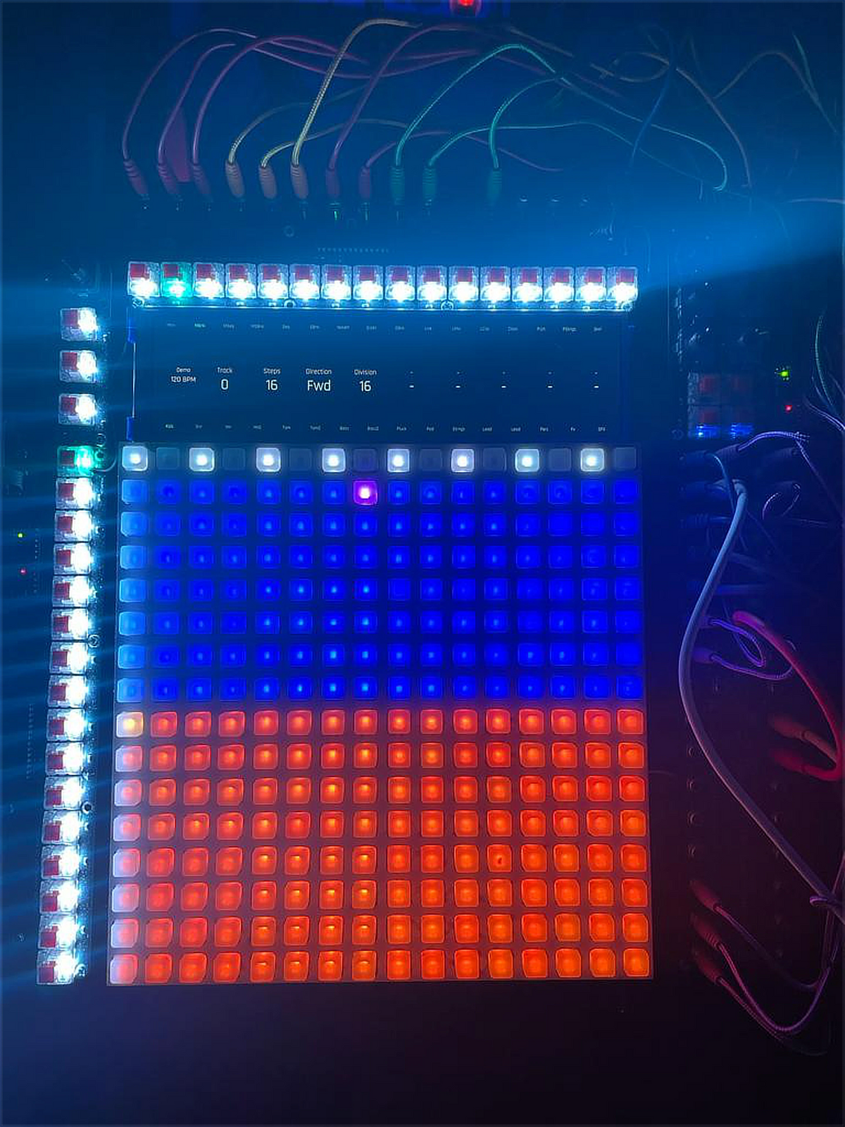
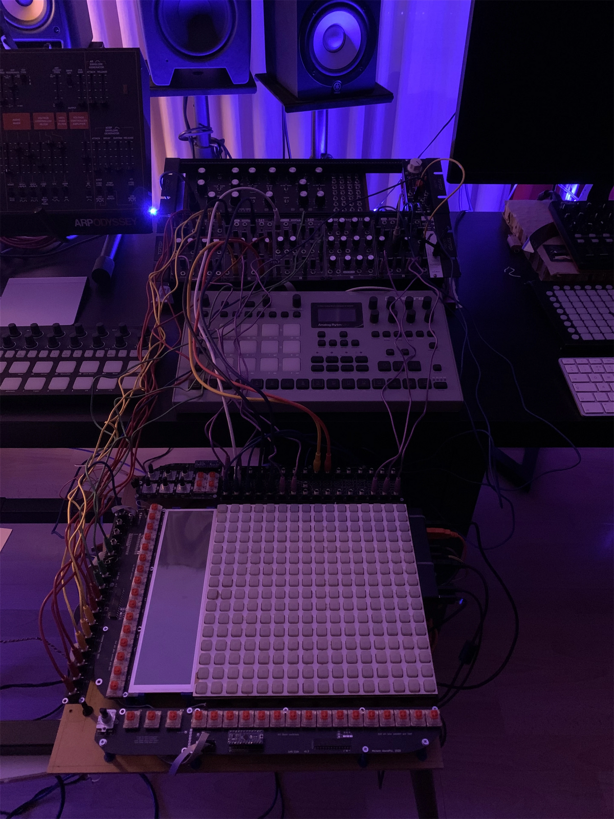
We were still trying very hard to make Reliq compact. The first layout followed the matrix very literally: inputs above the display, outputs, CV and gates along the right-hand side. On paper it looked elegant because the physical connections followed the same axes as the matrix, and it kept the overall footprint reasonably small.
We spent roughly six months discussing and thinking through that direction, followed by another six months designing enough of the electronics and mechanics to actually build it.
It took about three seconds to understand that it was an absolutely horrible idea.
As soon as we patched the prototype it looked like a spaghetti monster. Cables hung directly over the display, more came out beside the controls, and the top of the instrument became something we had to physically reach through. If we wanted to move it to another table, we first had to disconnect an absurd number of cables and then reconstruct everything again on the other side.
The drawing had made perfect sense.
Sitting in front of it with both hands, it was obviously wrong.
Around this time Zois had become much more involved in the mechanical and interface design, and he reasonably did not like the six contextual encoders on this prototype either. The idea had been that we would select or hold something on the grid and those six encoders would become the relevant parameters.
We had designed it this way partly because it saved space, and in theory it worked, but every time their function changed we had to follow that change mentally. Zois looked at it and said something along the lines of:
"What if we have sixteen encoders?"
Exactly as many as the repeating structures we were already working with: sixteen columns, sixteen inputs, sixteen outputs, sixteen tracks.
Michele and I more or less looked at him in horror.
Sixteen encoders did not just mean buying ten more encoders. It meant enough processor inputs to read them, more scanning, more PCB routing, more mechanical space, more processing headroom and another substantial redesign of a front panel we had already spent a long time developing.
But a good idea is a good idea.
And the more we looked at it, the more obvious it became that sixteen would be significantly better.
The connectors above the screen could leave the main interface entirely and eventually move towards the breakout-box concept, which is probably a story for another article. In their place, the encoders could follow the same horizontal geometry as the display and the pad grid underneath.
An encoder could sit at the top, its name and value appear directly below it, and the corresponding physical column continues into the grid.
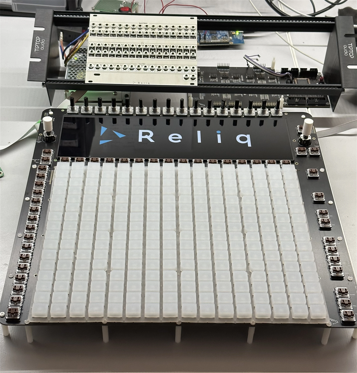
That sounded much more like the thing we had originally imagined.
Of course, sixteen encoders take up space.
We could not simply put them as close together as possible. Shafts have dimensions, caps have dimensions and hands definitely have dimensions. We needed enough room to grab and rotate one quickly without constantly hitting its neighbours.
For months, Zois' desk seemed to collect every encoder sample available on earth.
Different shafts, different caps, different diameters and slightly different mechanical feelings. We had some advantage because our hands were not the same size. Mine are relatively small, others around us had much larger hands, and friends visiting the studio were regularly recruited into trying different spacings whether they particularly wanted to participate in interface research or not.
The pads had the same problem too. They needed to be large enough to play quickly, slide across and hit several at once, but every extra millimetre repeats across sixteen columns. Pad width changed the grid width, the grid affected the screen, and the screen in turn constrained where those sixteen encoders could comfortably sit.
After a lot of physical prototypes, we slowly fine-tuned the relationship between encoder pitch, screen width and pad dimensions until it started feeling comfortable to play rather than simply fitting together on a CAD drawing.
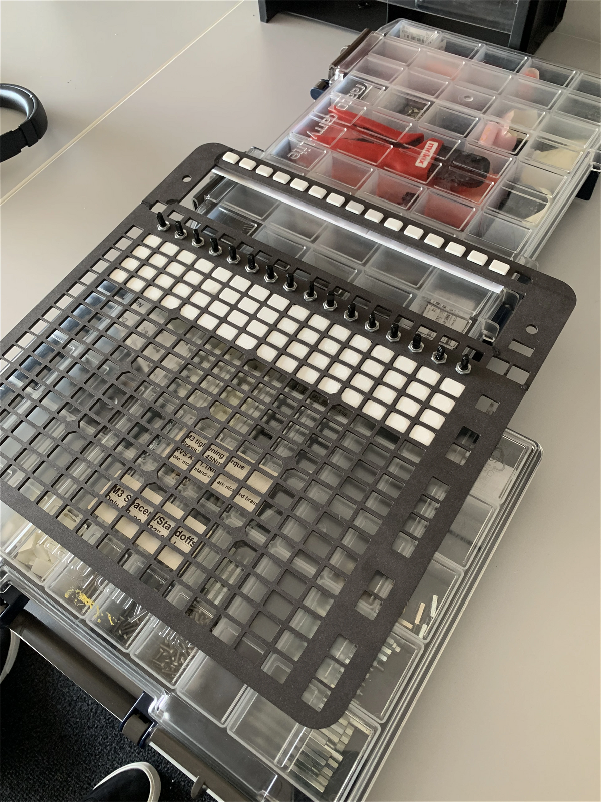
And that made the screen we had spent all those months learning how to drive obsolete.
We needed something wider, and we had also understood by then that we wanted considerably more resolution. If the display was going to show full names, parameter values and larger parts of the instrument at the same time, we did not want to end up compressing everything back into cryptic abbreviations simply because the screen was too small.
So the search started again.
We went through several suppliers and eventually managed to get closer to some of the very few manufacturers actually producing these panels. Exactly how some of those conversations happened is probably something better left outside a public article, but through that process we were shown a panel that was remarkably close to what we had been looking for.
It was bright, the colors were excellent, the physical proportions were almost right, and it had a resolution of 1920 × 515 pixels.
We managed to get samples.
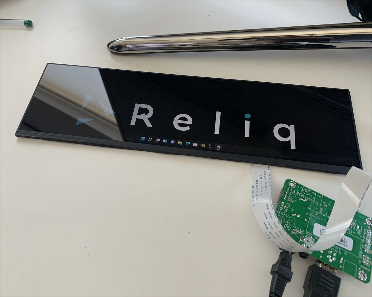
One slightly unusual thing about working with display panels at this level is that you do not always have every piece of electrical information before the sample is sitting in front of you. Some of the deeper technical material only becomes available as the project and supplier relationship progress.
So when the displays finally arrived and we got access to more of the information around them, we discovered exactly what we had bought ourselves into.
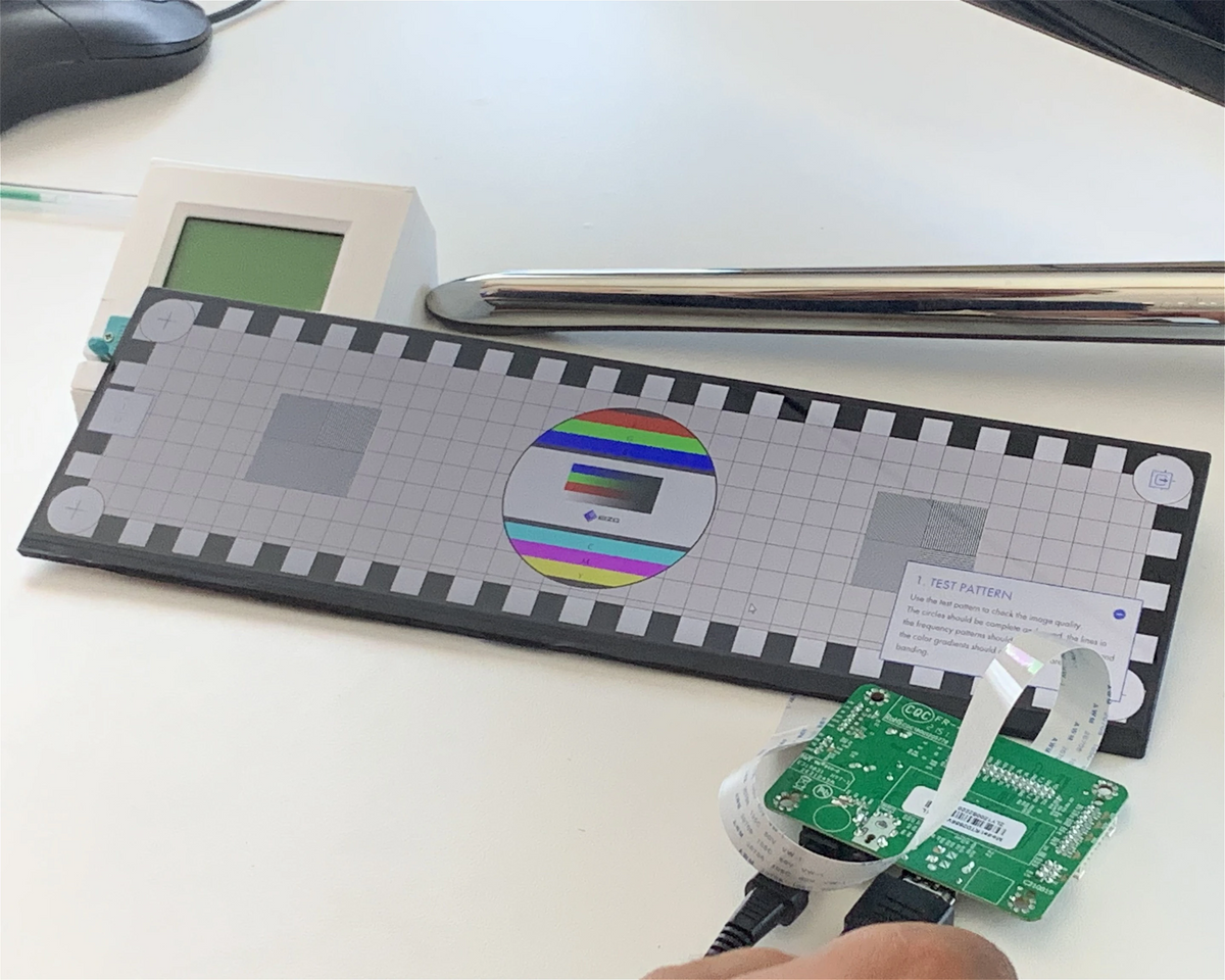
By then we had enough experience to be immediately suspicious of the number 515.
Processors generally prefer memory layouts that divide cleanly into regular boundaries, often powers of two, and display hardware tends to be designed around a relatively predictable collection of common resolutions. 515 was not exactly helping us.
The high-level interface first had to become an image somewhere in memory. Part of the visual layer was written using GLSL, a low-level graphics language that describes mathematical operations the GPU can execute directly. The final image then lives in one or more framebuffers, which are simply blocks of memory containing the pixels that are about to appear on the display.
The geometry of those framebuffers matters.
Every horizontal row occupies a certain amount of memory, commonly described through its line stride. The display hardware then moves through those rows continuously while keeping the whole frame synchronized. With our unusual 515-line geometry, assumptions that worked efficiently for more conventional resolutions suddenly behaved very differently.
Even changing the geometry from 515 lines to 514 could noticeably alter the performance because of how some of the divisions inside the graphics pipeline worked.
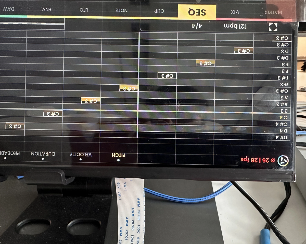
Then there is VSync.
A display draws frames continuously. VSync is essentially the synchronization point where the system knows one frame has completed and the next can be presented cleanly. Get that relationship wrong and you can get tearing, dropped frames or inconsistent latency between changing something and seeing that change.
We wanted the display to run fast enough that when we turned an encoder, the visual response felt connected to the movement of our hand. A screen can technically refresh at 60 Hz and still feel slow if some actions appear one frame later, others two frames later and occasionally something stalls altogether.
The geometry was only one part of it.
Electrically, the new panel also could not directly communicate with the display output available from the processing architecture we had already built.
By this point, we had already learned through the architecture work that the different jobs inside Reliq worked better when they had clear boundaries. Musical timing had its own protected domain. Analog control had another set of constraints. High-level application processing had its own space.
The display ended up teaching us the same lesson again.
Rather than redesigning Reliq's entire processing architecture around one unusual panel, we decided to isolate the display transport and build the missing hardware ourselves. What we needed was effectively a dedicated hardware display driver sitting between the application processor and the panel, translating between them while keeping the unusual requirements of the screen inside their own part of the system.
Finding components capable of doing this was also not exactly a walk in the park.
Eventually, we found a large semiconductor manufacturer in Taiwan with a component that looked capable of doing what we needed. Before we could properly start there were NDAs, technical discussions and quite a lot of paperwork, but eventually the components arrived together with the expected reference configuration.
Which, as was becoming somewhat traditional by then, did not work with our panel.
Again, that was not particularly surprising. The reference configuration demonstrated the manufacturer's known setup, while ours was very much our own. The difficult part was that many of the settings we needed were controlled through registers that were not all documented for us.
A register is basically a tiny configurable location inside a chip. Writing a particular value into one can change some very specific part of the hardware behaviour: timing, synchronization, electrical characteristics or one of dozens of other internal settings.
So for the following six or eight months, information arrived gradually. We would isolate a particular setting we needed to understand, explain why we needed it, receive another piece of documentation, test it and continue. In parallel, we reverse engineered enough of the behaviour to fill some of the gaps ourselves.
At the same time, we were designing the circuitry around these components and turning all of this into our own display hardware.
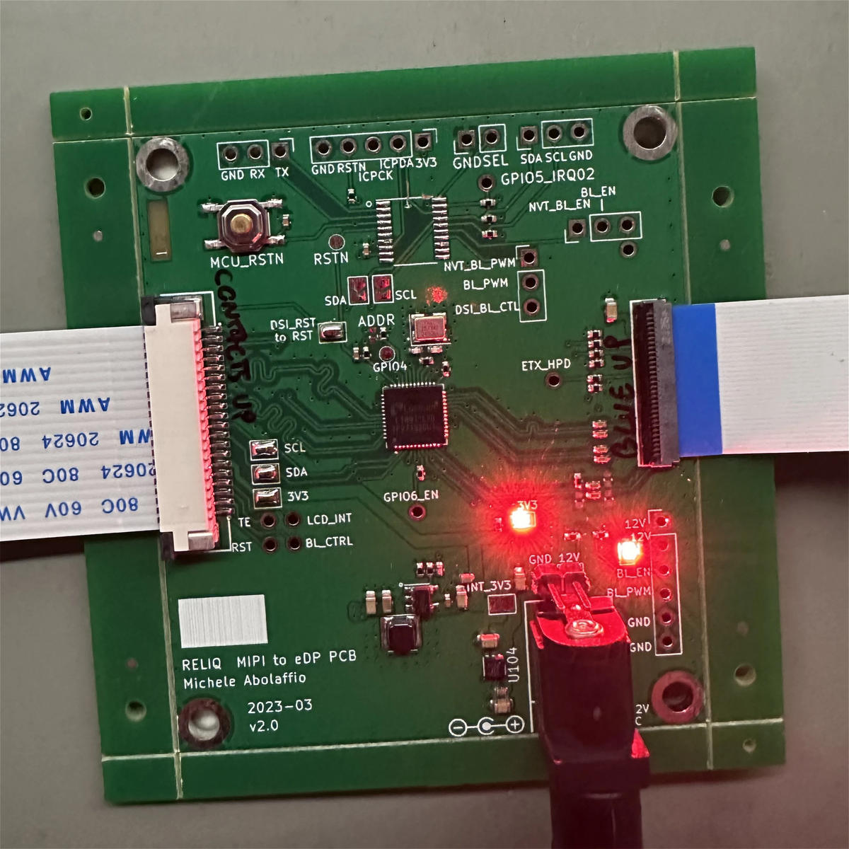
The first PCB, unsurprisingly, did not work, so we revised it.
The second version was almost worse because it worked some of the time. The panel would come alive for a few seconds and then disappear again. When developing new hardware, intermittent problems are some of the worst ones you can get because you do not even know which version of reality you are debugging.
Now we had to work out whether the problem was in our hardware, the configuration of the display driver, our software, the panel timing or some interaction between several of them.
Eventually, part of the answer turned out to be somewhere else entirely: there was also a fabrication or assembly problem on the board.
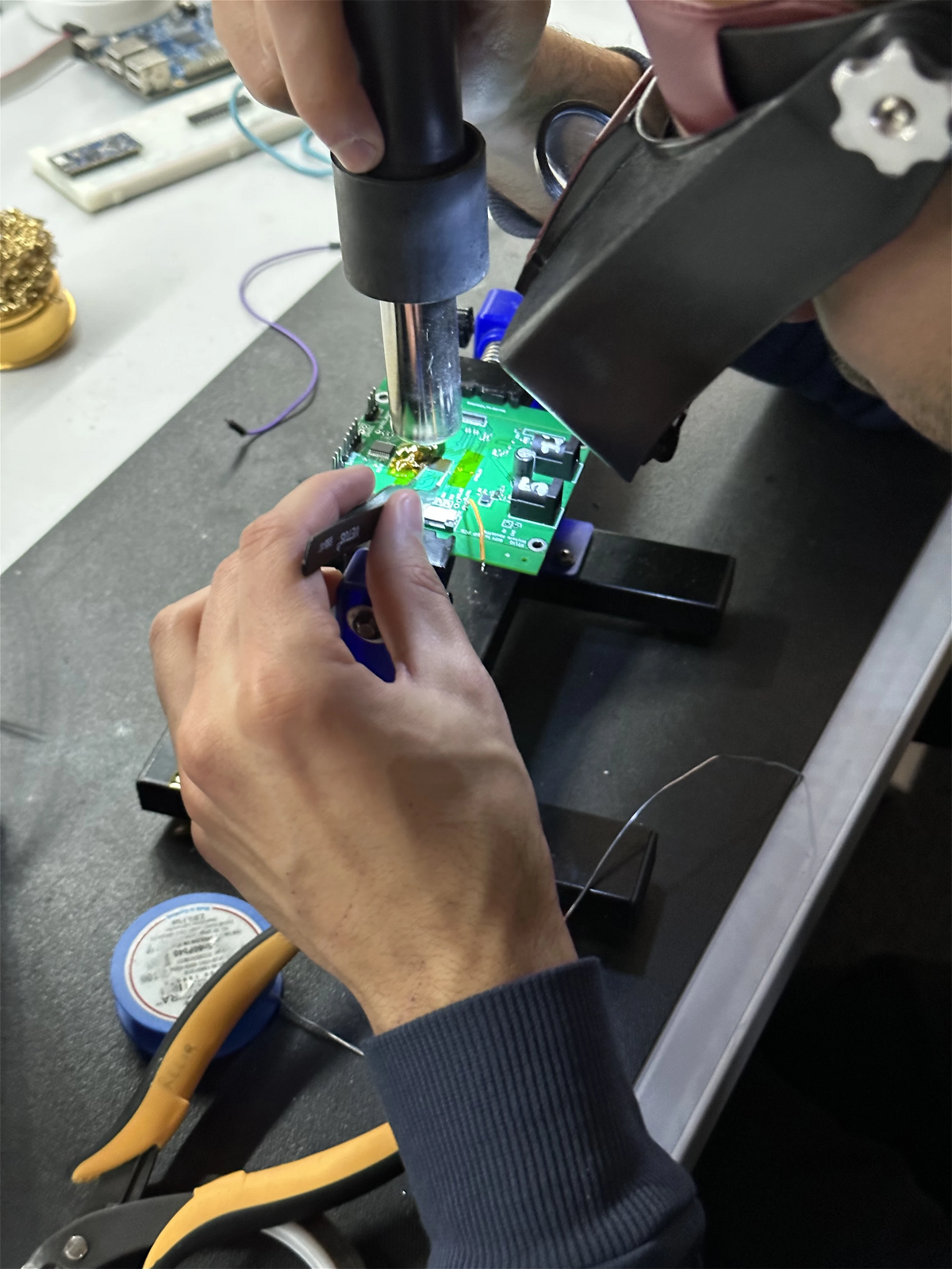
This is one of the difficult things about developing several new layers at once. There is no known-good chain to compare against.
The PCB is yours, the software is yours, the panel is unusual and part of the documentation is incomplete. Before debugging the actual problem, you first have to establish which parts of reality you can trust.
Even after the electrical path was finally behaving, though, we had only solved how to physically move pixels into the panel.
We still had to make the actual Reliq interface run on it.
This became another large part of the project and one that is mostly invisible when looking at the final instrument.
A high-resolution display can consume a substantial amount of processing power and memory bandwidth if you treat it casually, and Reliq had plenty of other work to do.
From the architecture side we had already given ourselves a very strict goal of preserving most of the available processing headroom so the instrument could continue growing for years.
We did not want the screen eating that budget. So a lot of the graphical work went quite low-level.
Parts of the interface were written in GLSL so that the GPU could perform the relevant graphical calculations itself rather than making the CPU draw everything. We built framebuffer handling around the panel's unusual geometry and modified parts of the processor-side display drivers where their normal assumptions did not match what we were doing.
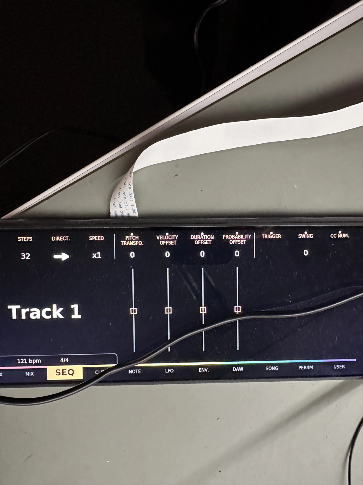
We also had to be careful about moving data around.
A single 1920 × 515 frame already contains close to a million pixels. Copy that image through memory several unnecessary times for every refresh and the bandwidth cost starts growing very quickly.
We wanted the shortest practical path from the graphical code, through the framebuffer and display hardware, into the physical panel.
And all of that had to remain synchronized.
The visual side could be complicated internally, but none of it was allowed to leak into the real-time side of the instrument. Drawing a waveform, changing pages or refreshing a parameter value should never have any say in when a MIDI event, gate or sequencer tick happens.
Through all this display work, while many other parts of the instrument were moving in parallel, we slowly started understanding what building Reliq was really going to be like.
It was clearly going to take much longer than we had imagined. Every time we thought we had reached the difficult part, something else appeared underneath it. But strangely, it was also incredibly enjoyable. We kept entering technical worlds we knew little about, spending months understanding them and then seeing another small piece of the instrument become real.
By early 2022, we had finally proved that the complete hardware path for this new screen could work.
The panel could initialize reliably, receive frames through our own display hardware and run from the processing system we had designed.
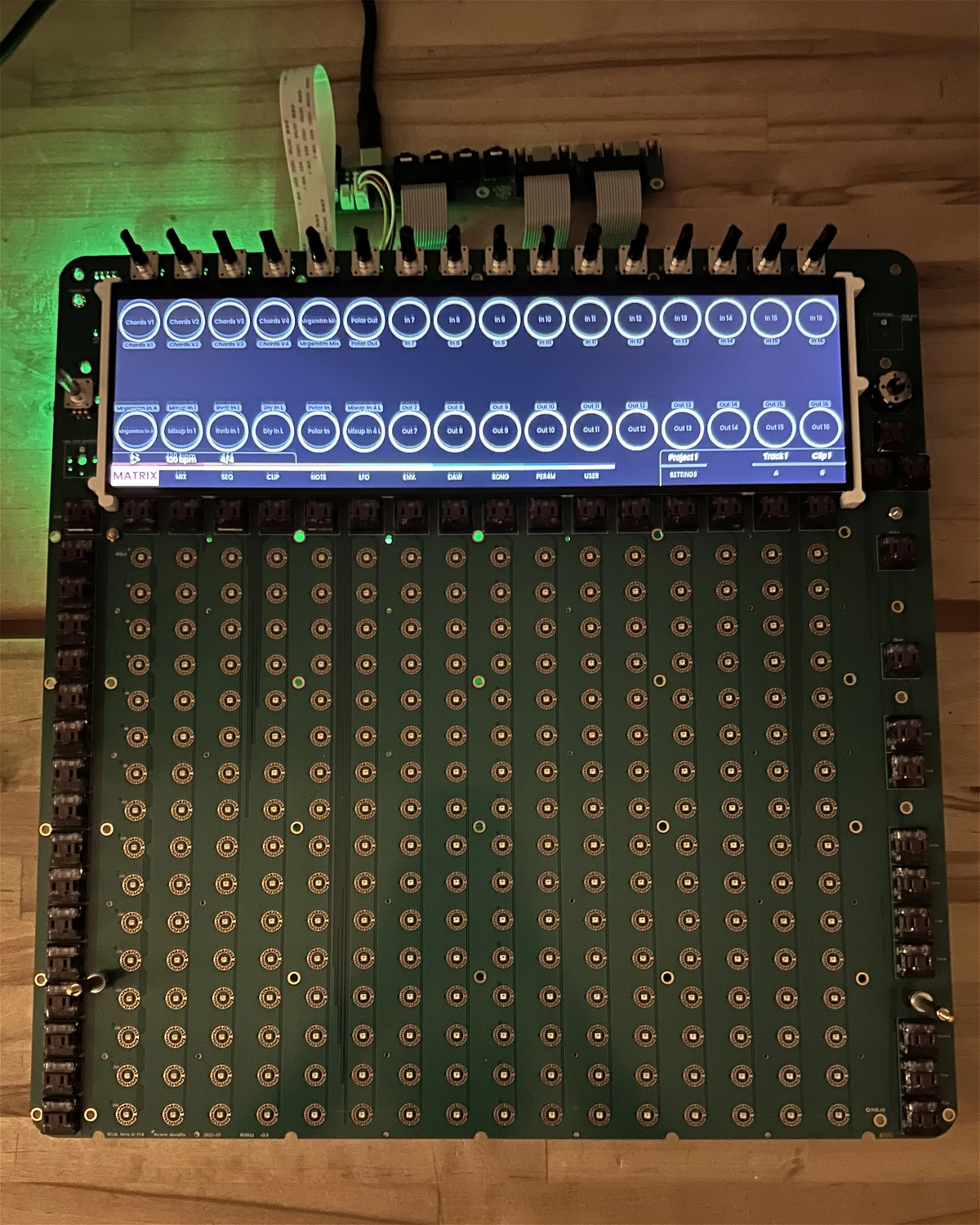
That was a big moment.
We also knew that this was only a proof that the path was possible. There were still months of graphics work, low-level software, driver modifications and optimization ahead before the screen actually behaved the way we wanted it to.
And even then, there was a much more uncomfortable question waiting for us.
Was the interface actually any good?
We had already spent roughly a year building one physical direction only to patch it together and understand within seconds that it was wrong. So when enough of the new prototype was finally ready to assemble, putting those pieces together was quite an exciting moment.
We mounted the sixteen encoders above the screen as we had been drawing them for months. Under the display sat the sixteen columns of the pad grid.
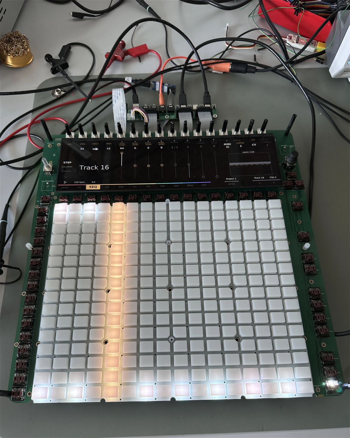
Then we started using it.
Thankfully, this time it finally felt like the pieces were falling into place.
When we turned an encoder, its context could appear exactly where our hand already was. We could change pages while keeping the same physical orientation because the screen changed but the controls did not move. We could see a detailed parameter and still have enough of the surrounding structure visible to know where we were.
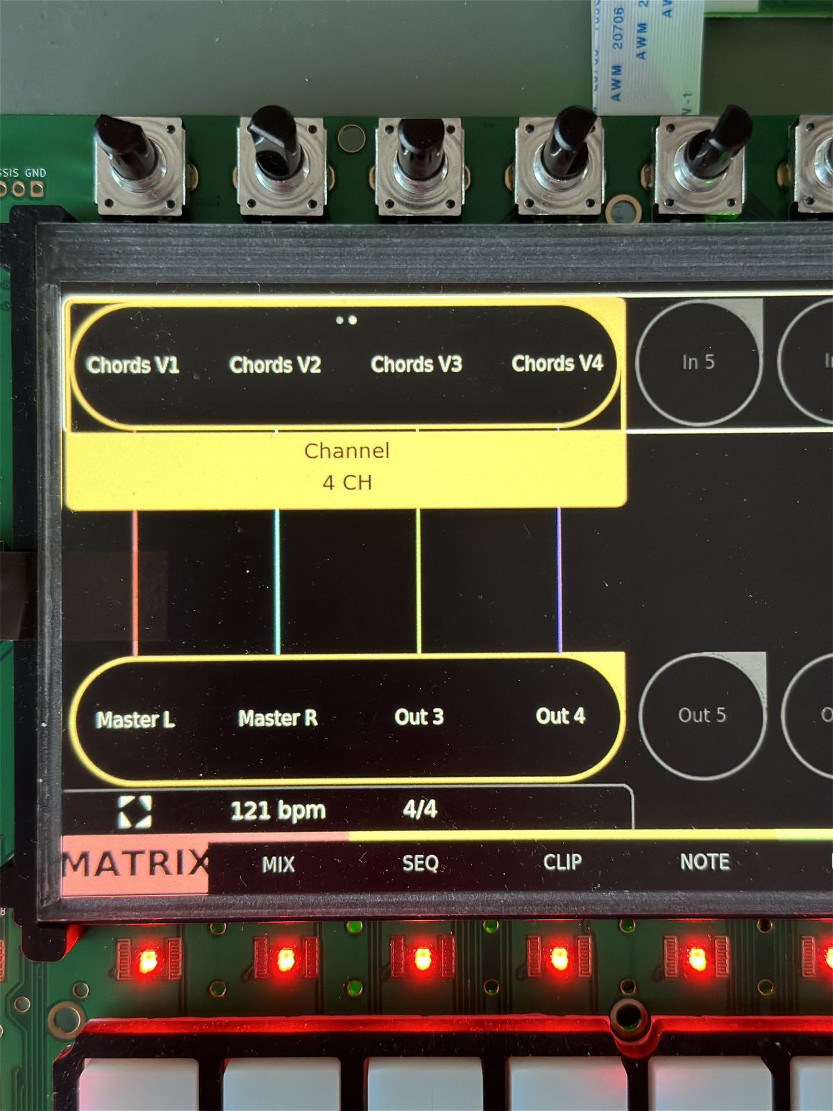
That bird's-eye view we had been thinking about years earlier was finally starting to get there.
The screen gave us direction and overview. The encoders gave us something immediate to grab. The pad grid stayed a physical landscape that our hands could learn over time. None of those elements had to carry the entire interface by itself.
This was only one part of what we had been trying to find from the beginning, but it was a part that finally felt right.
Once the electrical and software work was mature enough, a large part of the display development moved into mechanical and optical engineering.
We always knew that a bare LCD panel was not a finished screen.
Reliq was supposed to last for years, move between studios and stages and survive all the normal things that eventually happen to instruments outside a laboratory. The panel needed protection, but that protection also needed to remain readable from different angles and under very different lighting conditions.
We tested glass, protective films and various anti-glare approaches. Some protected the panel well but noticeably changed the image underneath. Reflections would improve while contrast became worse, or colors would lose some of the quality we had spent so much time trying to preserve.
Eventually, we found an approach that seemed workable enough to move towards production, but applying the protective layer itself required an extremely clean environment. A tiny piece of dust trapped above a large bright display becomes remarkably difficult to ignore once you know it is there.
Thankfully, we had access to a clean room here in the Netherlands, so for a period of time we were going there and assembling display protectors ourselves.
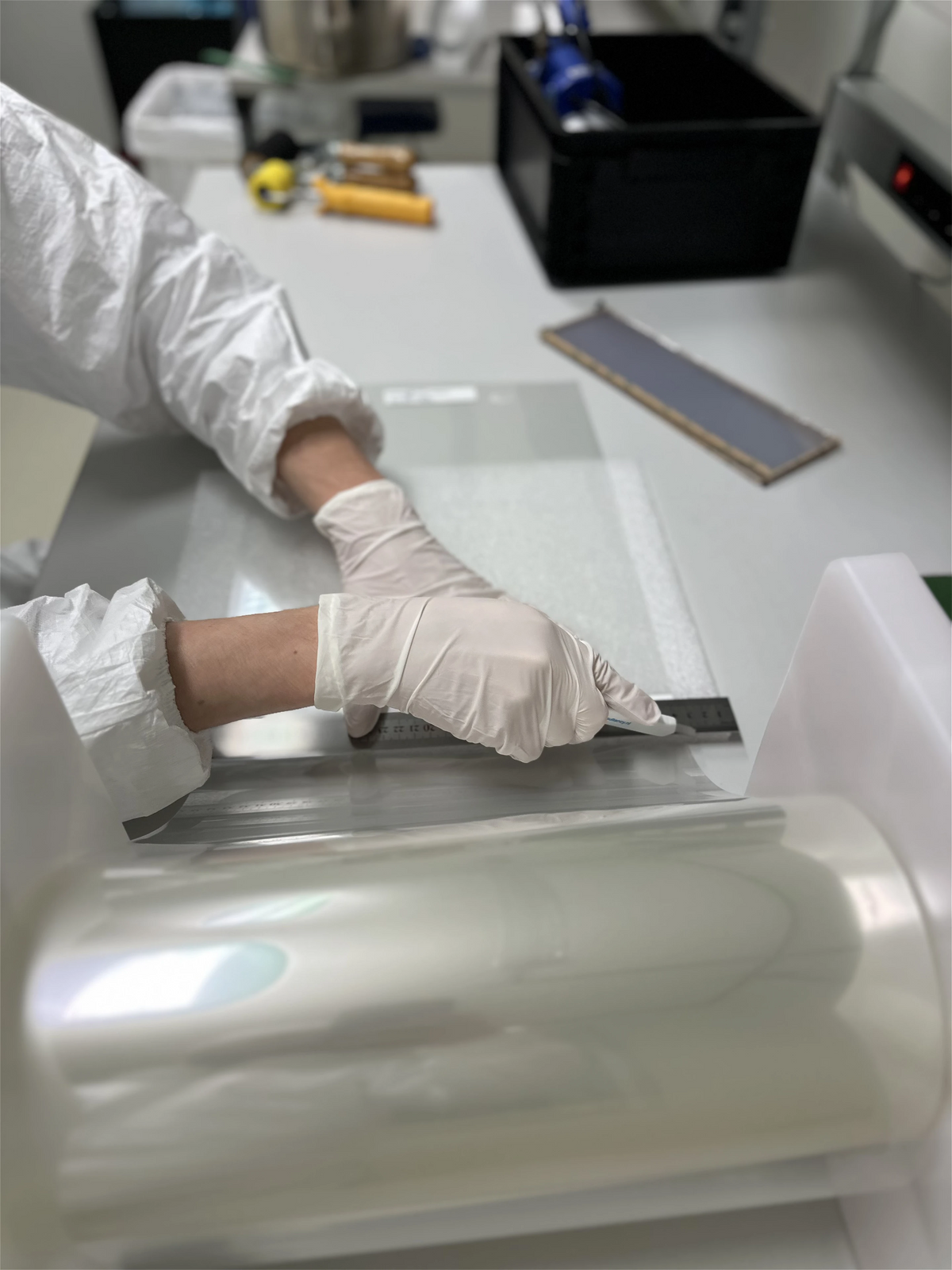
The process technically worked, but the margin for error was too high. A tiny alignment mistake or particle could ruin an expensive assembly, and even when everything went correctly, we were still not entirely happy with the optical result.
This came during one of the more difficult periods of Reliq development.
Several hardware and supply-chain issues were happening at the same time, and trying to solve all of them remotely through emails, samples and repeated shipments was becoming increasingly inefficient.
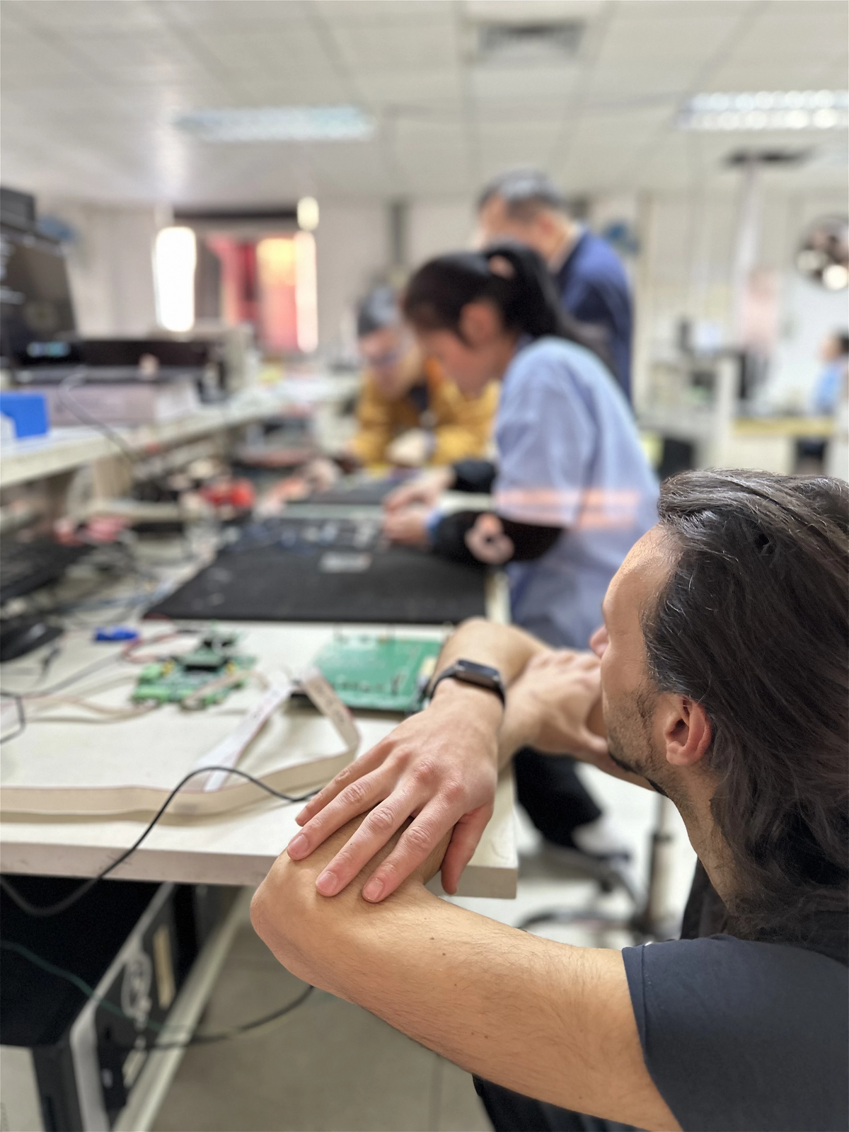
Eventually we decided that we needed to go to China ourselves and sit in the same room with the people making these parts.
During that trip we met manufacturers working with display assembly at a scale and level of experience far beyond anything we could reproduce ourselves. We already knew about optical bonding, but it was never something we realistically thought we could implement independently.
Optical bonding removes the air gap between the panel and its protective layer by bonding them across the entire surface with an optically clear adhesive. Besides mechanically joining the two, this dramatically reduces internal reflections between the surfaces and helps the finished display behave more like one optical object.
Talking directly with the manufacturers made us realize that our production partners could actually help us do this properly.
There was a catch, of course. It cost significantly more and it meant another delay.
By then, delays were not something happening privately in our workshop anymore. People were waiting for their Reliqs, and every additional change meant asking them to wait longer.
There was a lot of pressure around decisions like this because we genuinely did not want to keep moving the finish line.
At the same time, we kept reminding each other that if we had already taken this long, knowingly shipping something we were unhappy with just to recover some time made very little sense.
So we went ahead with the optical bonding.
Getting that process right took additional work, but when we finally saw the finished assemblies, the difference was enormous. Reflections were much better, the contrast stayed intact, and the protective surface stopped looking like another layer sitting above the image.
For us, that was worth the pain.
There were moments during those years when we genuinely wondered whether all this work around one display was worth it.
From an engineering perspective, the answer eventually became quite concrete. We had a 1920 × 515 panel refreshing at up to 60 Hz, a graphical interface that remained responsive under our hands, and enough separation in the architecture that none of this had to interfere with the clock, sequencer or the real-time musical events happening underneath it. The rendering pipeline, custom display hardware and drivers could do their work while still leaving the processing headroom we had deliberately reserved for Reliq to continue growing.
That was the technical result we had been chasing.
But it is not really the reason we think those years were worth it.
The reason is much closer to the question we had at the beginning.
We wanted to be able to focus on one musical action without losing sight of the rest of the instrument.
We wanted full names instead of abbreviations when there was room for them, context without having to memorize the context, and enough overview to understand where we were going before pressing the next button.
At the same time, we never wanted the display itself to become the instrument.
The grid, the encoders, the matrix, the screen and the architecture underneath them all solve different parts of the same problem. Take one away and something else has to compensate for it. Make one too dominant and the balance changes again.
Maybe that is one of the larger things those first years taught us about Reliq.
There was never going to be one processor, one screen, one interface idea or one clever feature that suddenly made it the instrument we had imagined. Most of the work was in finding the relationship between all of those pieces, and being willing to throw one away and start again when that relationship did not feel right.
The display happened to take us almost three years to find its place in that relationship.
There were plenty of easier screens we could have used along the way.
Looking at Reliq now, we are very happy we didn't.